6DOF Ultralight Robot Camera Arm
Summary
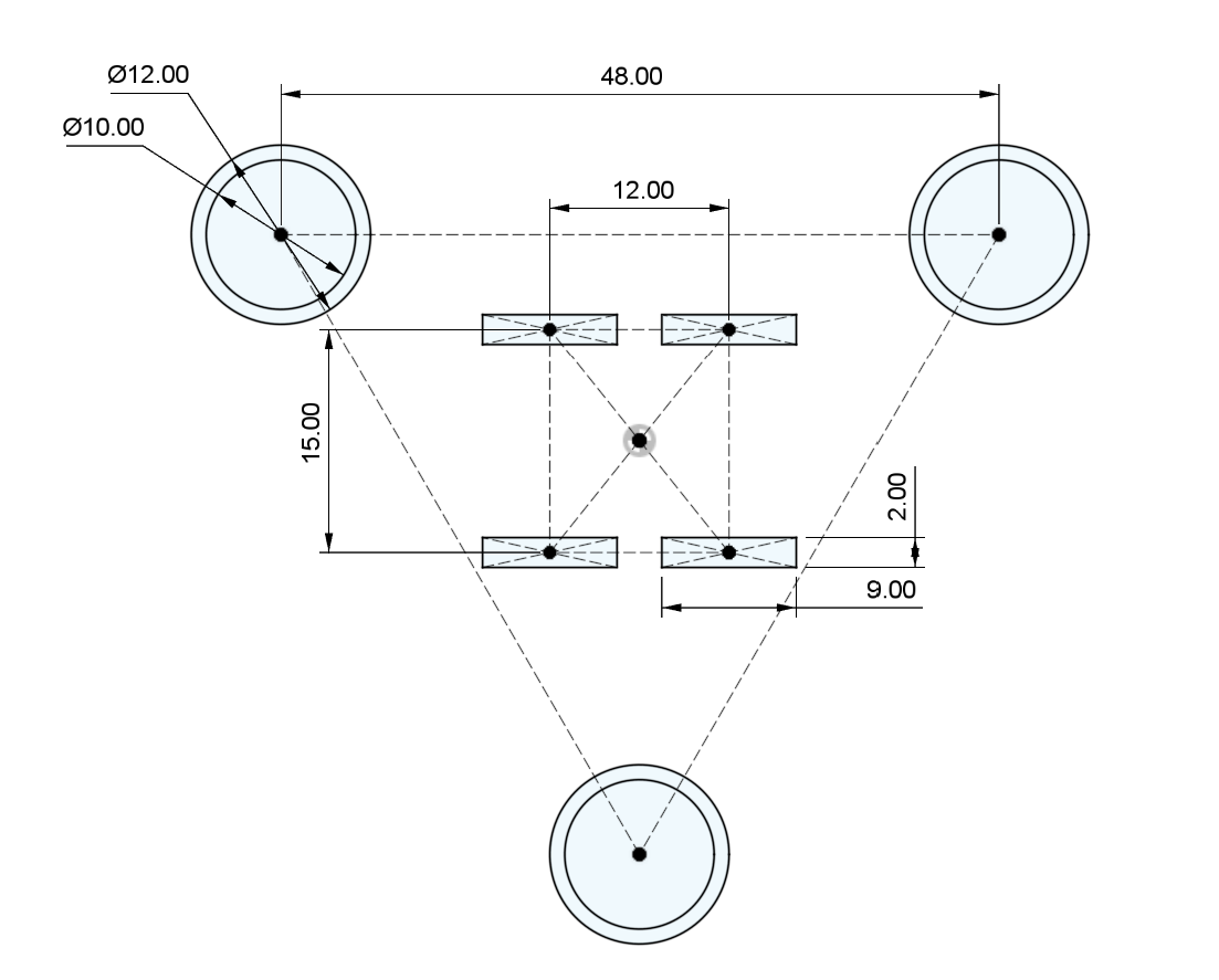
The goal of this project is to make an extremely rigid yet lightweight robot arm for phones, cameras, and other objects. Smoothness, strength, and low backlash are key, so it must be rigid and able to withstand the forces from the load and its own acceleration. Carbon fiber rods are extremely rigid and light, and they can be made even stronger together in a triangular configuration (shown below). ABS plastic 3D printed with high density will be used to join parts together. Side panels and fairings will be minimal to reduce weight/bulk and showcase the mechanics of the arm. Wires can be slipped through the carbon fiber rods as cable management to retain a sleek design.
 CAD Cross section (to scale). Circles are CF rods and rectangles are GT2 9mm belts for kinematics.
I want to make a camera arm to assist in making videos and time lapses with my 3d printer. While I’m very familiar with mechanical components and have dabbled with electronics in 3d printers, I have very little experience coding. With the complexity of a robot arm, code can’t just be copied from the internet and I will likely have to make a lot of it from scratch. Many robot arm project guides exist on YouTube already, but I want to go through the design process myself with my own ideas and goals. This project is a leap of faith, to see how much I can learn and achieve.
Plan
Build and Design Process:
- Design the arm in Fusion 360, including all electronics and hardware a. Design gear reduction mechanism, likely harmonic drive due to low backlash b. Ensure parts all fit together properly and in a satisfactory form factor
- Begin 3D printing test components to check tolerances for electrical and mechanical parts a. Test fit mechanical parts and 3d prints together for strength and rigidity b. If 3D printed parts don’t fit together properly, adjust and reprint to correct tolerances c. Test harmonic drive to ensure strength and minimal backlash
- Test electrical components components to ensure parts are working properly before assembly
- 3D print final components ready for assembly in ABS
- Begin assembly!
- Test motors to ensure they are strong enough to support the weight
- After assembly, simulate 1:1 scale model in Blender to perform inverse kinematics simulations
- Perform basic tests for smoothness and positional accuracy after kinematics calculations
Tools (hardware and software):
- Screwdrivers (duh)
- 3d printer and filament (ABS and TPU)
- Soldering iron
- Fusion 360
- Blender (kinematics simulation)
Inspiration and learning from Jeremy Fielding and 稚晖君 on YouTube
Budget
What materials will you need for your project? Where will you get them? How much does it cost? Please include all materials, including components you already own. Make sure to factor in shipping costs and sales tax.
Many of the materials will be components commonly used in 3d printers, which I already own some of and am very familiar with. For parts I don’t have, Amazon and online 3d printer part stores will cover most if not all of the mechanical and electrical components. https://docs.google.com/spreadsheets/d/1o8EGZSA9DsgLYJZ-idwo8wbahZMI09PmzNXrt5GQjlU/edit#gid=0